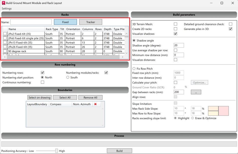
1) To start designing your PV layout, select the “Build Ground Layout” option in the Ground-mount section. This will open a popup where you can start defining your layout.

In this popup you first need to select one or multiple racks that you want to use in this layout. Choose between fixed or tracker systems and then select the required racks. (For more information regarding racks, consult the 'racks database' support page).
2) Next are the row numbering options. You can choose to number the rows and/or the modules and racks as well. Then choose to start the numbering in the North or South.
The last option “continuous numbering” allows you to number different layout boundaries together. If this remains unchecked then all boundaries will have a separate numbering.
3) The next step is to select the boundaries in which you want to build this PV layout. Press “select on drawing” to set one boundary at a time. Now click on a point inside a boundary to select and a popup will open.
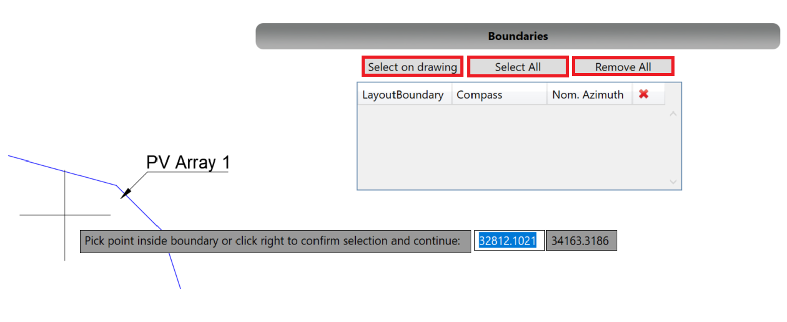
In this popup you need to specify how you want your racks to be placed. First of all to which side you want to align the racks to. The second option determines the placement of smaller racks if those have been selected. So supplement left or right means placing smaller racks to the left or right. With the alternately option the smaller and bigger racks will alternate.

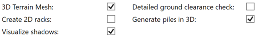
4) The next step is to define certain build parameters:
- 3D Terrain Mesh: Select this option if you want to place the racks on the ground mesh surface (if available).
- Create 2D racks: This option allows you to create racks in 2D instead of 3D. This gains you a lot of performance for large scale projects.
- Visualize shadows: When this option is selected shadows will be projected on the project as a line.
- Detailed ground clearance check: By default the minimum height for rack placement will be taken into account for the 4 corners of a rack. But when this option is selected the minimum height will be respected for every point of that rack. This is useful for projects on a very sloped terrain.
- Generate piles in 3D: This is the option if you want to have the piles of the racks in 3D or not.
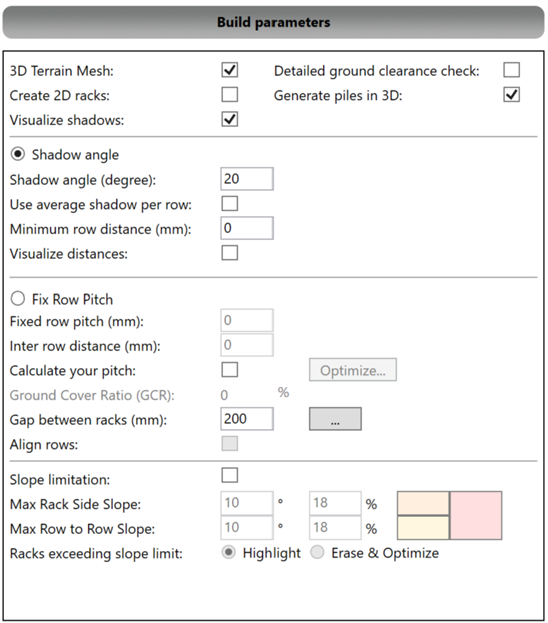
Now there are 2 options for placing the racks:
- Shadow angle: This option allows you to enter a shadow angle. Then the program will take that shadow angle and the terrain into account and will calculate the shadow that is created by the racks. The row distance will be determined by the furthest reaching shadow to create a shadow free system. There is also the option to use the average shadow distance for placement. Now you can specify the minimum row distance required and determine if you want to use the visualize distances option, this will project the row pitch and inter row distance on the project.

- Fix row pitch: Here you can enter fixed values for rack placement. First of all the row pitch (distance from front of one rack to the front of the next one) and inter row distance (distance between different racks).
You can calculate these values as well with the calculate pitch option. To do this you need to check the calculate pitch option and press optimize, this will open a popup. In this popup you need to specify the DC power you want to reach and the minimum and maximum row pitch you want to have. This will calculate the values for you and they will be filled in automatically when you press ok.
5) Next is the Ground-coverage ratio (GCR) this is the ratio of module area to land area. It describes the proportion of system area that is used to collect sunlight.
This is shown as a percentage and changes according to the row pitch that is entered.

Now define the spacing between racks that are in the same row and choose if you want to add extra gaps by selecting the additional gaps option.
In the popup that opens you can specify at which amount of columns or rows you want to create a bigger gap in the layout. Of course you need to specify the gap size as well.

You can also check the align rows option if you want to align rows between different layout boundaries.
6) The last step before building our layout is to choose our slope limitations. Here you enter the max slope you want to have for the placement of the racks. Then the racks that exceed that slope when being placed are highlighted with specific colors or erased when that option is selected. You can define the max slope from side to side or from row to row.


7) Now set the positioning accuracy and press build.
The positioning accuracy sets the interval distance for searching the best position to place your racks. It can be set from low (5000mm) to high (100mm).
You can also save all of these settings for future projects. Select settings and save to save this as a preset.

Video Tutorial