![White full logo.png]](https://help.virto.solar/hs-fs/hubfs/White%20full%20logo.png?height=40&name=White%20full%20logo.png)
Generate a configuration
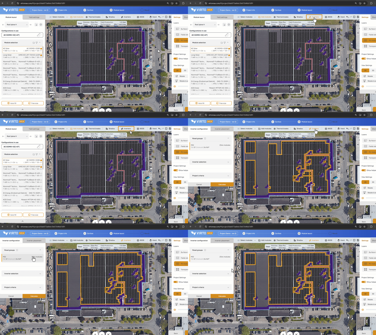
- Complete the module layout and open Inverters.
- Review the listed Panel Groups and the number of modules in each group.
A panel group is defined by tilt/azimuth and slope for roofs and by row for carports & ground setups
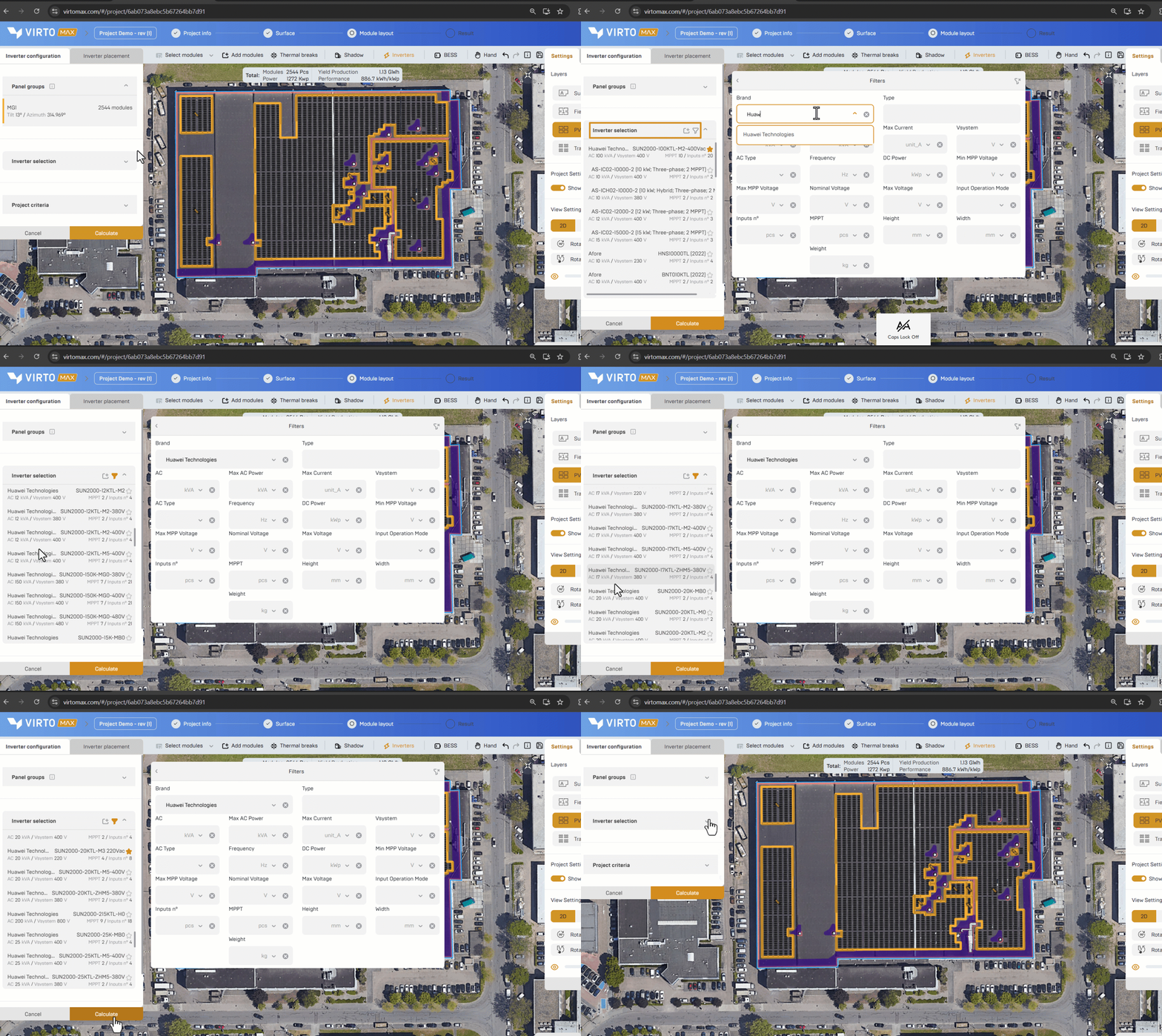
- Select one or more inverter models.
- Use the filtering options in the upper-right corner of this section. To keep preferred inverters at the top of the list, click the star icon next to each one.
- If the inverter you need is not listed, you can add it to the database. Click here for step-by-step instructions.Select one or more inverter models.
- In Project Criteria,
- Preferred String Lenght: To determine the valid string length range for the selected module and inverter combination the following calculations are done:
- The minimum string length ensures that the string voltage remains above the inverter’s minimum MPPT voltage at high module temperatures (70°C). The value is always rounded upward to the nearest whole module.
- The maximum string length ensures that the string’s open-circuit voltage does not exceed the inverter’s maximum input voltage at low module temperatures(-10°C). It’s always rounded downward to the nearest whole module.
- Allow Y-connectors: Select Yes or No, depending on whether this is part of your configuration.
- DC/AC range: Use the slider to set an acceptable DC/AC range between 0.5 and 2 for your project. Only configurations within this range will be shown.
- Preferred String Lenght: To determine the valid string length range for the selected module and inverter combination the following calculations are done:
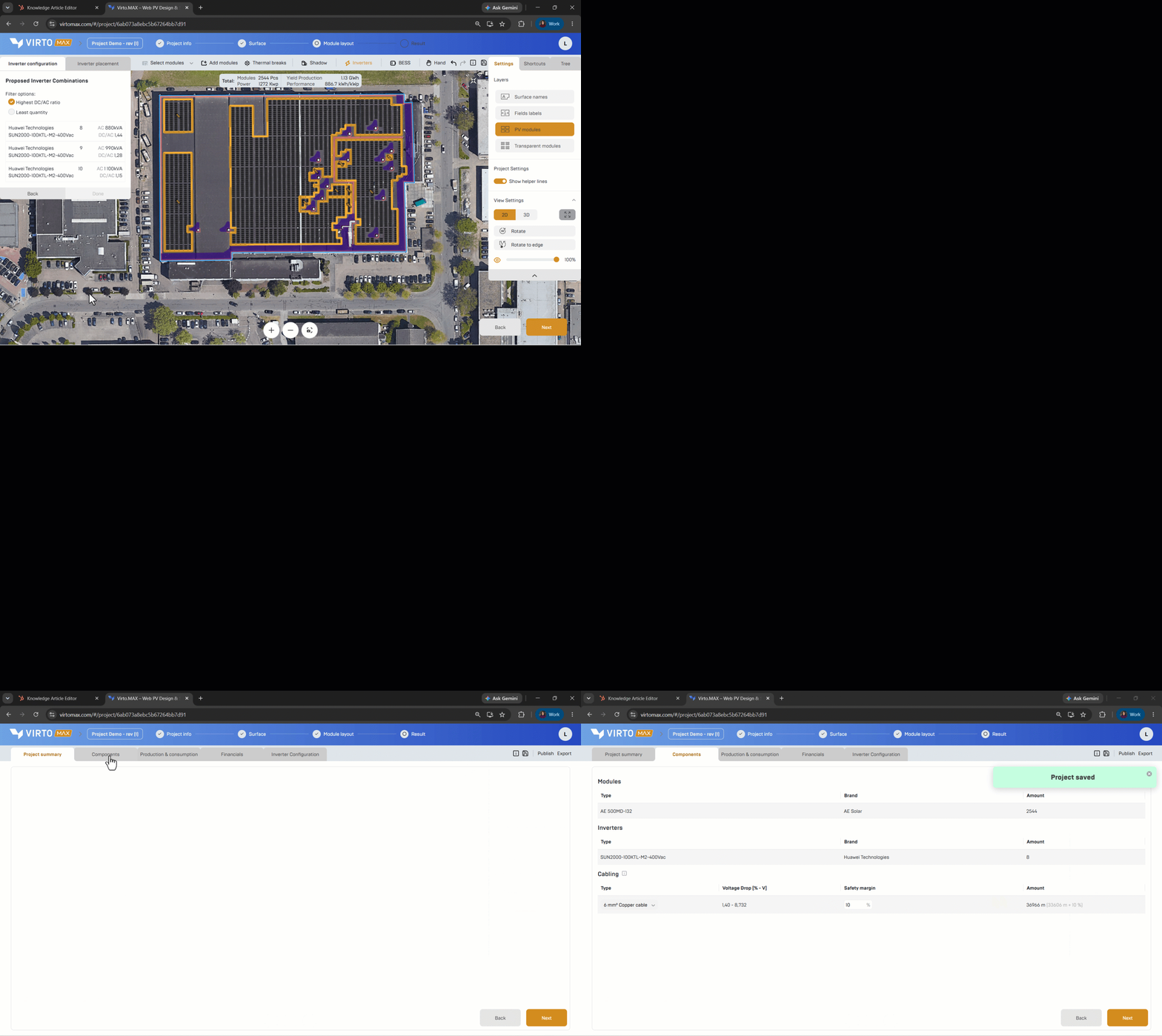
- Select Continue to generate valid combinations.

- Sort or filter the proposals by the highest DC/AC ratio or the lowest inverter quantity.
- Select the preferred combination and confirm with Done.
Place the inverters
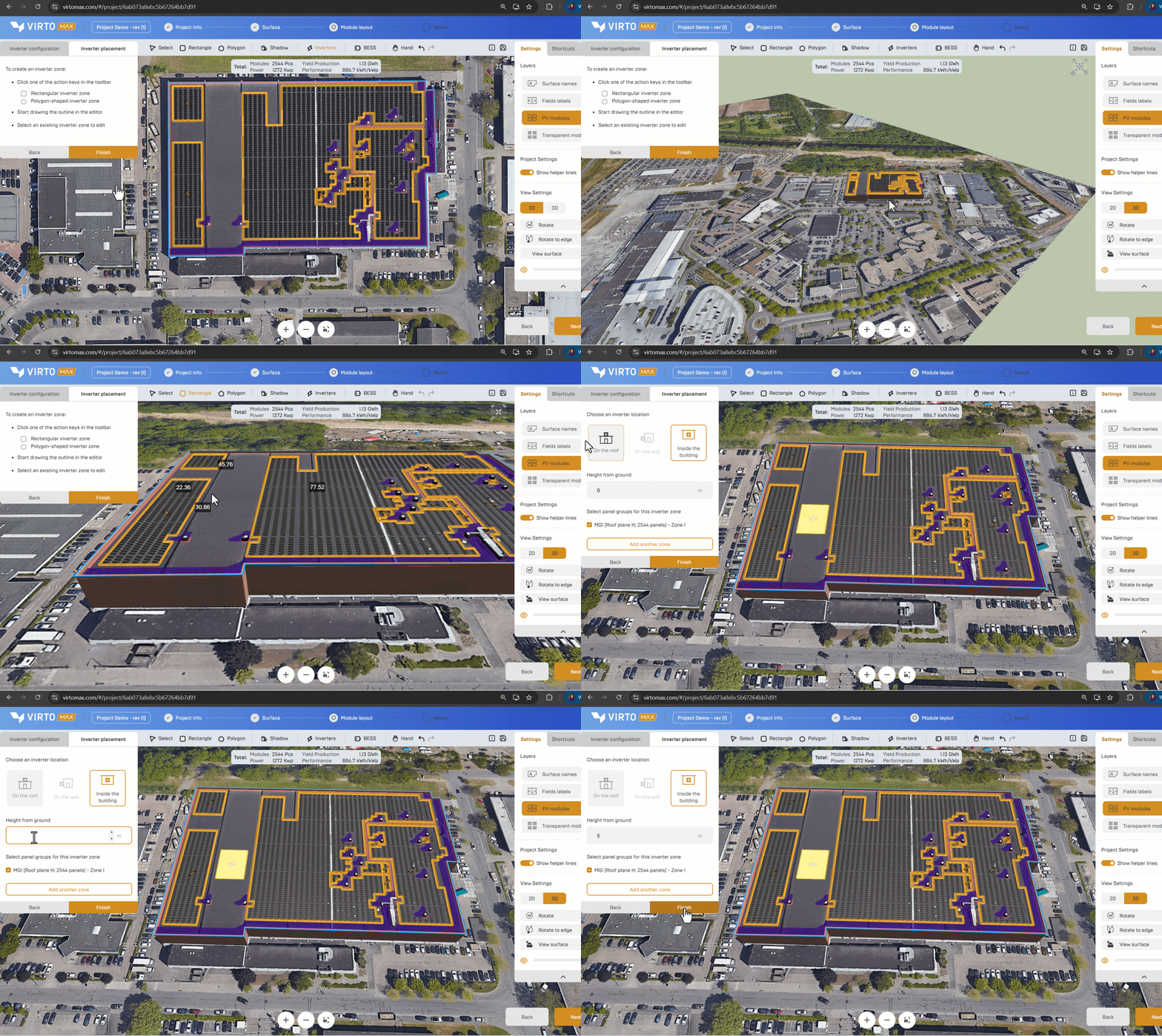
- In the toolbar, choose Rectangle for a regular shaped or Polygon for a custom shaped inverter zone.
- Draw the intended inverter location on a roof, wall, internal area, or site zone supported by the project model.
- Select the module group linked to this inverter location to support the cable size & length estimation.
- Add another inverter zone or confirm the placement. Now the estimated cable sizes and lengths are added to the component list. All created inverter zones will become visible in the editor, sharable links and pdf reports
Good to know: The suggested configuration supports early technical and commercial decisions. Final stringing, protection, cable routing, and compliance checks must be completed in the detailed engineering phase.
Next step: Estimate cable lengths and sizes or Review the project overview and create a report.