Pile generator
Configure and generate 3D piles for your racks
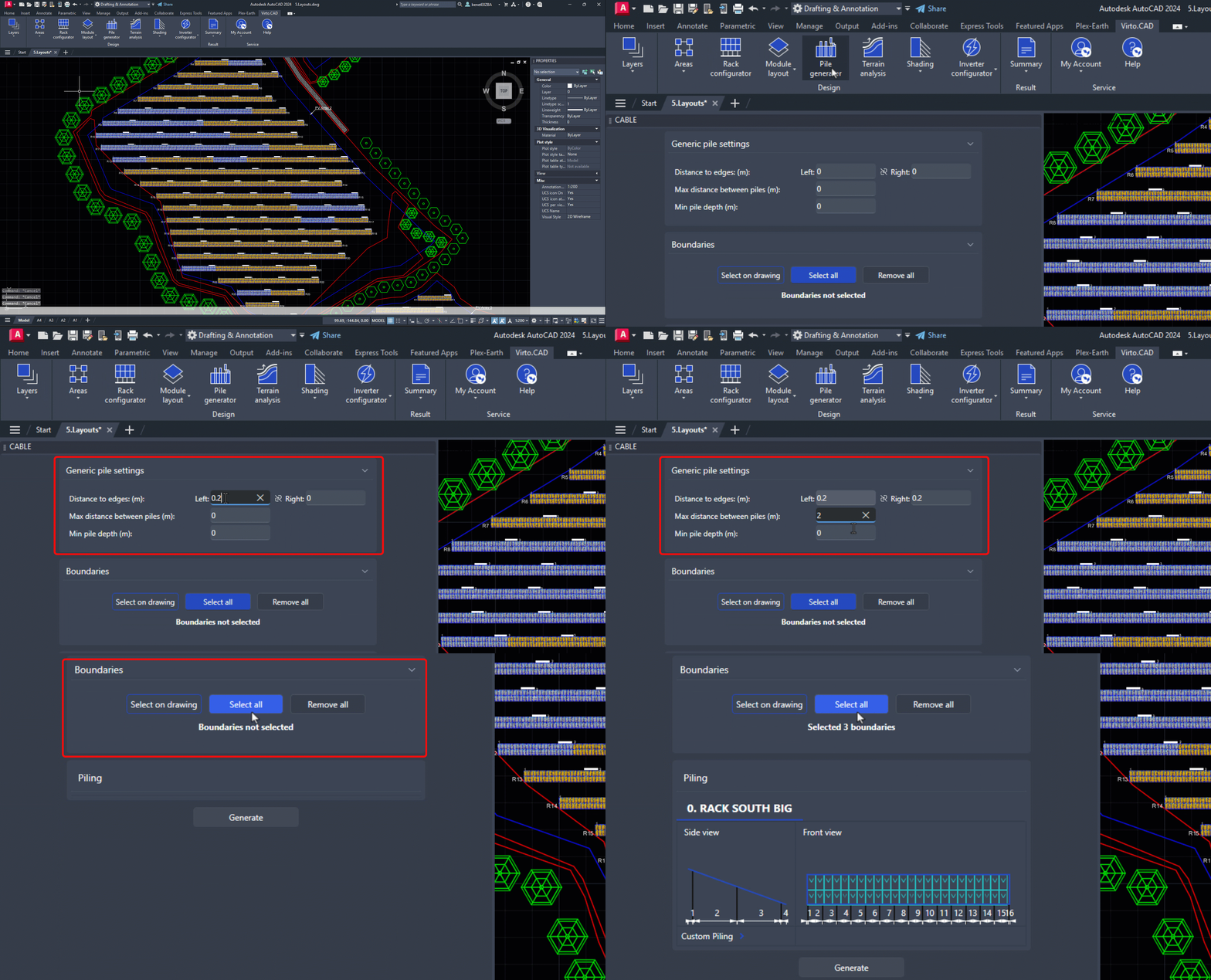
Once you have completed the Ground Layout for your project, you can move on to inserting Piles. To begin, find the Pile Generator option on the VirtoCAD ribbon.
Upon selection, a pop-up window will open, allowing you to customize the parameters for your Piles.
In this section, you will need to specify the following parameters:
- Distance between edges: The distance measured from the edges of the rack to the locations of the first and last pile placement.
- Max distance between piles: The maximum distance between piles that the software will use for automatic placement. You will have the option to customize this distance in the subsequent steps.
- Min pile depth: Minimum depth of piles into the ground.
Next, you will define the boundaries to which the pile parameters will be applied. You can do this by either selecting each boundary individually on the drawing or by choosing all boundaries within your project at once.

PILE CUSTOMIZATION
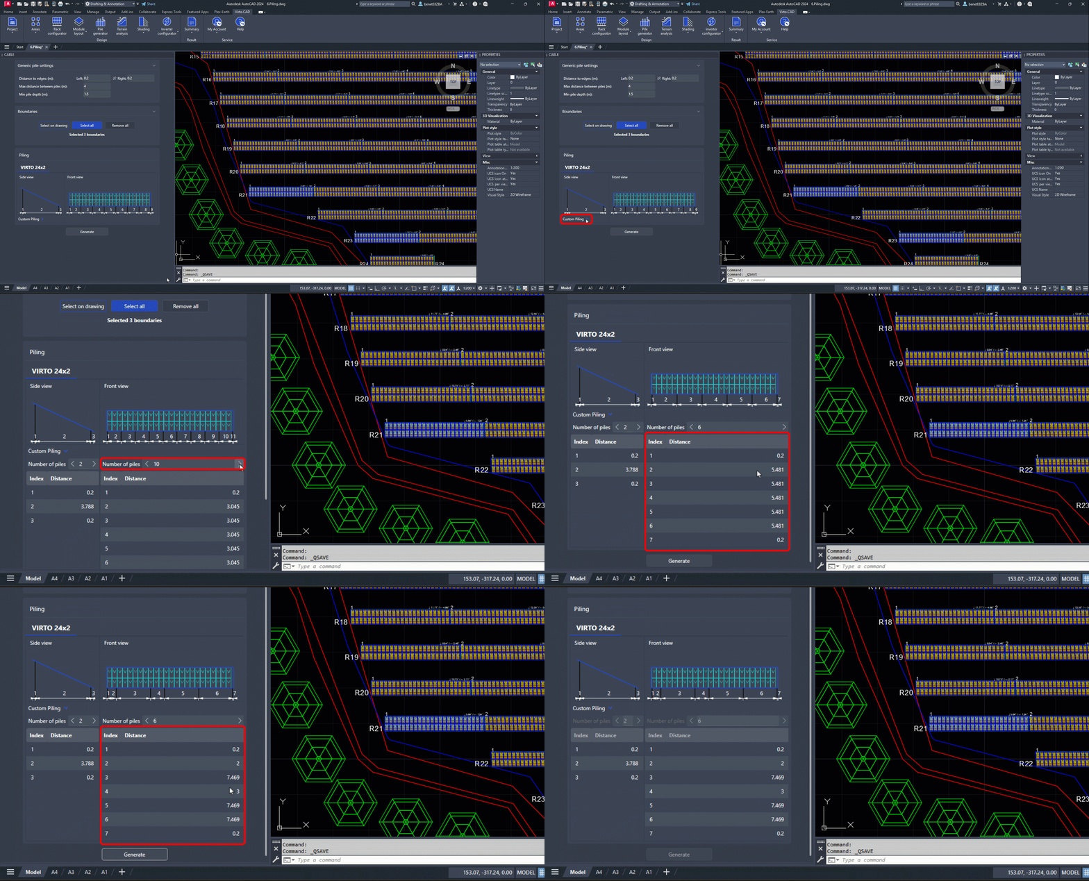
To customize the piling, simply click on the Custom Piling drop-down menu. This feature enables you to adjust both the distances and quantities of the piles for the side and front views of the selected rack.
The software will automatically calculate and display the necessary number of piles based on the Max distance between piles you specified earlier, ensuring they are evenly spaced. However, you have the flexibility to customize the spacing to meet the specific requirements of your project.

Once you have completed customizing the piles for each rack type, you can proceed by clicking on the Generate button.
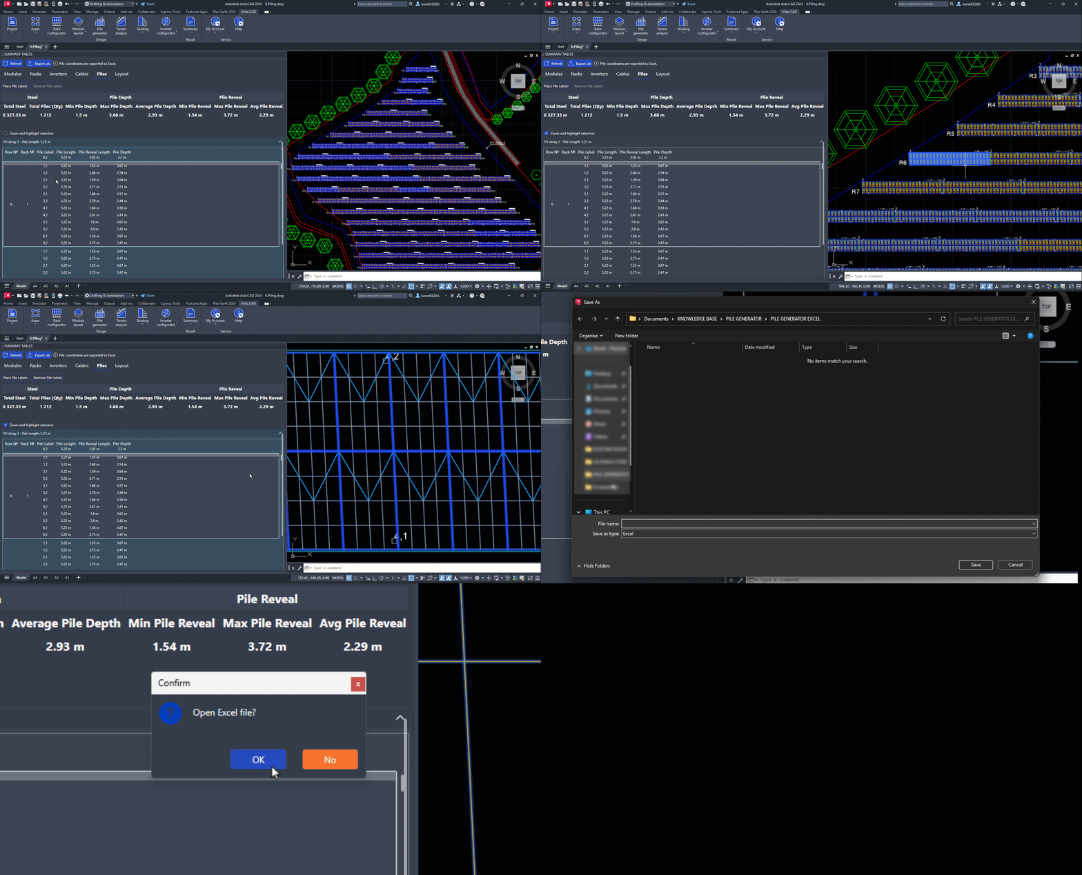
Immediately, the Summary Tables window will appear, providing you with detailed information for each PV Array's piling, including the Total amount of Steel (Pile Quantity/Length), Pile Label, Pile Length, Pile Reveal Length and Pile Depth.

To locate a specific rack, you can enable the Zoom and highlight selection feature. Simply double-click on the rack number you wish to find within your drawing, and the software will zoom in on that particular rack for easy identification.
You can also add or remove labels for each pile in your drawing by selecting the Place Pile Labels option.
Finally, to retrieve the coordinates for each pile, simply select the Export option. This will enable you to download an Excel file that contains all the necessary coordinate information.

By rotating your view, you can effectively visualize the 3D representation of the piles within your drawing.
