In the VirtoCAD ribbon you can select the “String mapping” option. This will open a new ribbon.


On the right side of this ribbon you can locate the settings option. Here you must define some string settings before actually starting the stringing process.
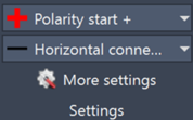
You can select to either start with plus or minus polarities and you can choose between horizontal or vertical connections. The “More settings” option opens a popup.
Here you will be able to choose the preferred wiring type and customize the visualization.
In the Common section some customizable options can be found:
- Type: Select the structure you are currently working with (South or East-West)
- Minimum gap: Define the minimum spacing between modules before the program will use interconnection cables.
- Dimension A/B: Customize how strings will be drawn on the modules according to the dimensions shown in the preview window on the right.
- Polarity text height: Set the size of the text at the polarities.
- String polyline width: Set the thickness of the string polyline
- Polarity offset: Add an offset for the strings starting from the middle point of the modules
- Polarity rotation: Rotate the polarity indicator and text.
- Text color: Set the preferred text color.
- String highlight color: Set the color that will be used to highlight strings when performing certain actions.
In the preview section you can define what the preview window on the right should look like. This way you can really mimic the module placement on your project.
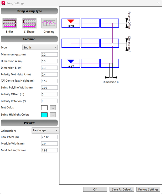
Finally on the bottom you can press OK to finish the setup.
There are also options to save your configuration as default for future projects or reset to the factory settings to undo all changes.
After completing this setup you can start stringing your project.