![White full logo.png]](https://help.virto.solar/hs-fs/hubfs/White%20full%20logo.png?height=40&name=White%20full%20logo.png)
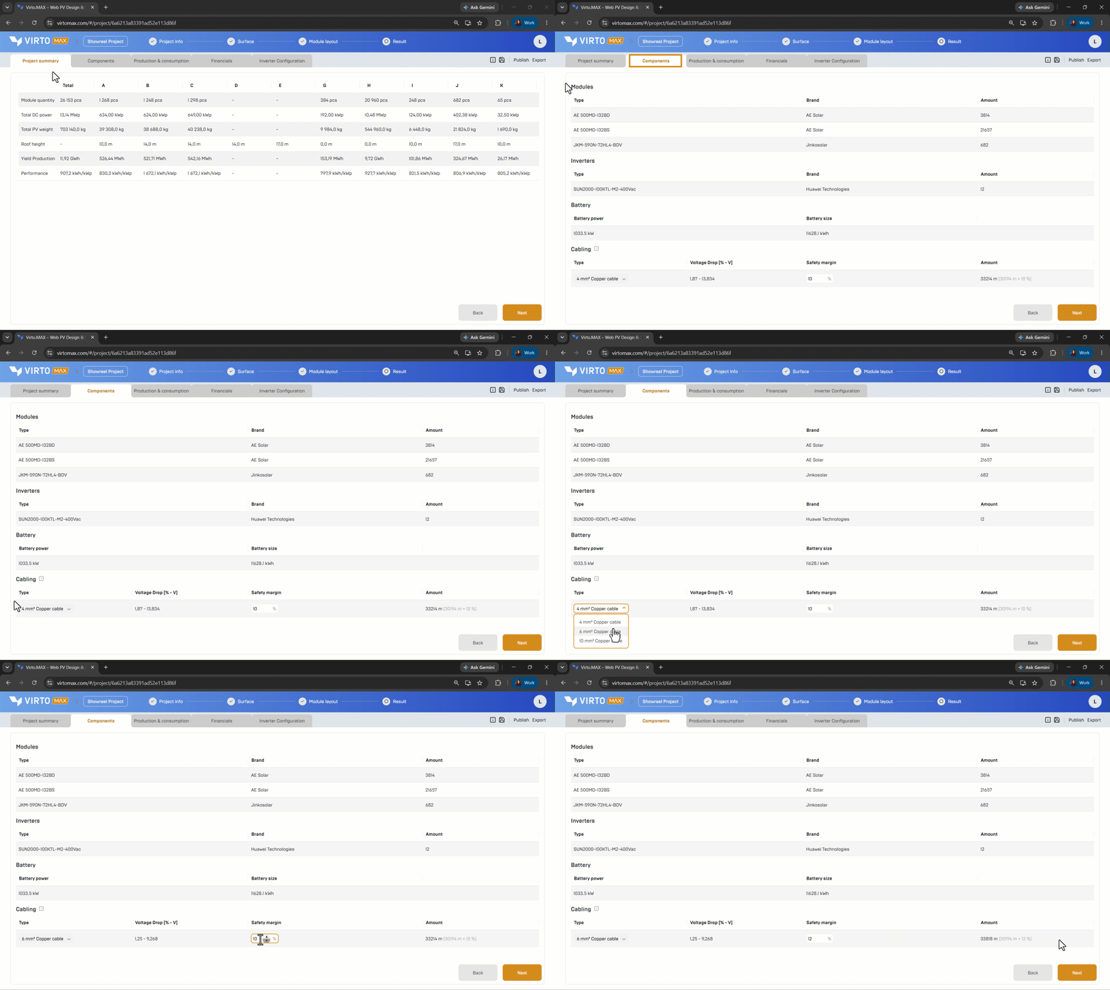
When completing the module layout, doing the inverter configuration and placing an inverter zone, the cable lengths and sizes will be estimated.
- Open the component view and go to Cabling.
- Review the applicable cable type & cross-section
- Enter the required safety margin.
- Review the calculated cable quantity. The result can be included in the exported PDF report.
Cable-length estimation method
Virto.MAX estimates an average cable path for each string from the array to the inverter.
The geometry uses:
- a: length of the PV array.
- b: width of the PV array.
- c: horizontal distance from the nearest module to the roof transit.
- d: vertical distance from roof level to the inverter or cable-tray level.
- e: final horizontal distance to the inverter.
- StringLength: number of modules in one string.
- ModuleSize: the relevant module dimension for the selected orientation.
The longest estimated one-way path is:

The shortest estimated one-way path is:

The expected one-way length per string is the average:
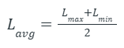
The system estimate multiplies the average path by the number of strings and applies the configured safety margin.
Cable size estimation method
We first calculate the average array voltage drop in Volts
ΔV = 2 × Lavg × (R / 1,000) × Impp
In this formula:
ΔV is the average voltage drop in volts.
Lavg is the average one-way cable length in metres.
R is the cable resistance in Ω/km.
Impp is the module/string current in amperes.
The factor 2 represents both the positive and negative DC conductors.
Dividing by 1,000 converts Ω/km to Ω/m.
Only copper cables are offered. The resistance used in the calculation depends on the selected cable cross-section according to the IEC norms.
|
Cable cross-section |
Copper resistance |
|
4 mm² |
5.06 Ω/km |
|
6 mm² |
3.39 Ω/km |
|
10 mm² |
1.95 Ω/km |
To convert this value into the average array voltage drop in percentage, we first calculate the operating voltage of one string:
Vstring = N × Vmpp,module
The voltage drop is then divided by the string voltage:
ΔV% = (ΔV / Vstring) × 100
When a project contains multiple arrays, the average project voltage drop in percentage is not a simple average. Each array is weighted by its average number of strings:
Project ΔV% = Σ(Array ΔV% × Array strings) / Σ(Array strings)
Arrays with more strings therefore have a greater influence on the overall project result.
To calculate the cable size, the calculated Average Project Voltage Drop is checked against a maximum threshold of 2%. If the result is higher than 2%, the tool proposes the next available copper cable cross-section and recalculates the voltage drop using the lower cable resistance.
The available recommendation sequence is:
4 mm² → 6 mm² when the Project Voltage Drop with a 4 mm² cable exceeds 2%.
6 mm² → 10 mm² when the recalculated Project Voltage Drop with a 6 mm² cable still exceeds 2%.
The tool stops at 10 mm², which is the largest cable cross-section currently offered. If the Project Voltage Drop remains above 2% with a 10 mm² cable, no larger cable is proposed automatically.
Actual cable resistance increases with temperature and varies with conductor construction. Use the cable manufacturer’s declared resistance and the applicable electrical standard for final engineering.
Good to know: This is an early-stage estimate based on simplified routing geometry. It does not replace detailed cable routing, ampacity, protection, short-circuit, thermal, or compliance calculations.
Next step: Review the project overview and create a report or Export to Virto.CAD and PVsyst.